

If done right, the plastic part design for injection molding can reduce the percentage of defects and wasted material. In fact, the decisions you make at the design stage often determine whether the part will run smoothly in production or cause constant issues later on.
Every detail matters in this process, including wall thickness, draft angles, radii, gates, ribs, and release features. All of them influence how a component behaves during and after molding. Sometimes, even a small oversight can lead to poor product quality or damaged parts.
In this guide, you will learn why design for injection molding is important and how to do it smart.
What Is Design for Injection Molding
Design for injection molding is the process of adapting a component layout so that molten material can fill the tool, cool uniformly, and be released. To successfully do it, you need to consider the product requirements and the practical limits of the molding equipment. Additionally, you need to keep the tool construction and material behavior in mind, as they can affect the final layout.
A proper design also focuses on wall thickness, draft angles, corners, undercuts, and other structural elements. All of these affect how the mold will interact with the material and how the filling will cool down in the process. Because of that, plastic mold design is often done during the part engineering and DFM review, where engineers identify manufacturability risks before the actual tooling.
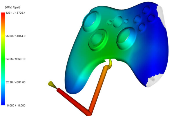
Important notice: even the best preparation doesn’t remove all the production challenges. Instead, it makes them noticeable and avoidable much earlier. Simulation and engineering review can show whether the part is likely to fill, pack, cool, and release within an acceptable processing window.
How to Design a Part for Injection Molding
The key fundamentals in an injection mold design guide include draft, wall thickness, coring and ribs, core-cavity layout, undercuts, and gating/ejection. All of these affect how likely the molding is to produce a high-quality part at an acceptable tooling cost.
Draft Angles and Radii: Getting Parts to Release Cleanly
Draft is a slight taper applied to walls that run in the direction of the mold opening. Without enough draft, the component can drag against the tool surface during ejection. This may cause scuffing, deformation, or damage to textured areas.
A starting draft of 0.5 degrees may work on short, smooth surfaces, but 1 to 2 degrees is more practical for many applications. Deep walls and textured finishes usually need more. The required angle depends on surface depth, material shrinkage, feature height, and the location of the parting line.
Corners also affect performance. Sharp internal corners disrupt melt flow and create a high stress concentration. Rounded transitions allow material to move more smoothly and spread loads across a wider area. External radii should follow the internal corner so wall thickness remains reasonably uniform.
These decisions form part of the design-for-manufacturability. A good DFM review checks release direction, corner geometry, and tool access before the shape is approved. Small changes at this point can prevent extensive tool corrections later.
The Importance of Wall Thickness
Wall thickness affects filling pressure, cooling rate, shrinkage, and structural behavior. Thick areas cool more slowly than thin areas, which can lead to voids, sink marks, and warp. Very thin sections may freeze before the cavity fills and may require higher pressure to produce consistently.
Uniform walls are therefore preferable. Where thickness must change, the transition should be gradual so material does not stop abruptly or cool at sharply different rates. The table below provides general starting ranges. Actual limits depend on flow length, resin grade, fillers, part size, and production requirements.
| Material | Typical wall thickness range |
| ABS | 1.2 to 3.5 mm |
| Acetal, POM | 0.8 to 3.0 mm |
| Acrylic, PMMA | 0.6 to 12.7 mm |
| Nylon, PA | 0.8 to 3.0 mm |
| Polycarbonate, PC | 1.0 to 3.8 mm |
| Polyethylene, PE | 0.8 to 5.0 mm |
| Polypropylene, PP | 0.6 to 3.8 mm |
| Polystyrene, PS | 0.9 to 3.8 mm |
These ranges are guidelines rather than guaranteed limits. Thin-wall applications may fall below them when the machine, material, and flow path support the required pressure. Large or highly loaded components may need thicker walls, but adding material should not replace proper structural engineering.
Wall thickness also affects cycle time. The thickest area often controls how long the component must remain in the tool before ejection. Reducing unnecessary mass can therefore improve output as well as cosmetic quality.
Coring Out and Ribbing to Avoid Thick Sections
Coring removes unnecessary material from thick regions while keeping the external shape. A solid boss or block can often be hollowed out so its walls match the surrounding section more closely. This reduces cooling differences and lowers the risk of voids, sink marks, and warp.
Ribs can restore stiffness after material has been removed. They are usually kept thinner than the adjacent wall because overly thick ribs may create visible sink marks on the opposite surface. Their base should blend into the wall with a radius to reduce stress concentration.
Ribs also need enough draft for release. Closely spaced ribs may trap heat or make cooling difficult, so spacing and tool access should be reviewed together. The most effective layout provides the required stiffness without creating a cluster of heavy sections.
Proper coring and ribbing help maintain strength while reducing material use. They can also shorten cycle time because the component cools more evenly.
The Core-Cavity Approach to Plastic Mold Design
The core and cavity are commonly described as the B and A sides of the tool, or the bottom and top halves. The cavity usually forms the visible outer surface, while the core forms internal features and areas that remain on the moving half during mold opening.
A core-cavity approach to plastic mold design divides the geometry in a way that simplifies machining and release. Instead of machining a deep pocket around the entire component, engineers may create the exterior with one half and the interior with the other. This can reduce manufacturing time and make polishing or texture work easier.
The split also affects appearance. Parting lines, gate marks, and ejection marks should be positioned away from important cosmetic areas where possible. Placing functional details on the appropriate side can improve release and reduce the need for complex mechanisms.
Early coordination with tool design specialists helps confirm parting line position, shut-offs, inserts, and machining access before the tool layout is fixed.
Undercuts: When They’re Necessary
An undercut is a feature that prevents straight removal in the main opening direction. Side holes, hooks, internal threads, and certain snap features are common examples. These shapes may be essential for function, but they add mechanical complexity to the tool.
Slides, lifters, collapsible cores, or unscrewing mechanisms can release undercuts. Each option affects tool size, maintenance, lead time, and reliability. Moving features also need enough clearance and support to withstand repeated pressure.
Undercuts should therefore earn their place in the component. A side opening may sometimes be moved to the parting line, while a hook may be reshaped so it flexes during ejection. When the feature cannot be simplified, its release method should be evaluated before tooling approval.
Simulation does not replace mechanical tool review, but injection molding simulation can show whether added slides, inserts, or geometry changes affect filling, cooling, and deformation.
Gating and Ejection: Getting the Part In and Out of the Mold
The gate is the opening through which molten resin enters the mold cavity. Its size, type, and location influence pressure, filling balance, weld lines, and the appearance of the gate vestige. A poor position may force material through a long or uneven route, increasing the risk of short shots or visible flow marks.
Gates are often placed where material can reach thicker sections before flowing into thinner walls. However, the best location also depends on cosmetic requirements and how the component will be trimmed or assembled. Multi-gate layouts can improve filling but may create additional weld lines.
Ejector pins push the cooled component away from the core. Their force needs to be distributed across areas strong enough to resist marking or distortion. Large surfaces may require several pins, a stripper plate, or an ejector sleeve. Pin marks should be placed on non-cosmetic areas when possible.
Gate position and ejector pins must be planned together because both affect tool layout and release behavior. We also recommend considering venting, runner balance, and cooling around these locations.
Need support before committing to tooling? Moldflow Software can review part geometry, material behavior, filling, cooling, and deformation risks, so changes can be made while they are still economical
Special Design Features to Consider
Now that you know the basics of how to design for injection molding, let’s talk about some extras. Special features add function, simplify assembly, or improve appearance, but they also introduce manufacturing constraints. Snap fits need enough flexibility to engage without breaking. Living hinges must survive repeated movement. Textured surfaces affect release and may require additional draft.
These details should be reviewed against the selected material and the component’s end-use conditions. A feature that performs well in one polymer may fail when stiffness, temperature, or chemical exposure changes. Early analysis helps balance functional performance with moldability and reliable production.
Understanding Snap Fits
Snap fits allow two components to lock together without screws or adhesives. The most common form uses a flexible cantilever that bends during assembly and returns toward its original position after passing a retaining feature.
Successful performance depends on several connected factors:
- Material selection: Flexible polymers can tolerate more strain than rigid or highly filled materials. The chosen resin should match the expected number of assembly cycles and the operating environment.
- Engagement angle: An entry angle of approximately 30 to 45 degrees often provides a practical balance between assembly force and controlled deflection.
- Retention force: The return surface must hold the assembly securely without making service or disassembly unnecessarily difficult.
- Wall thickness: Abrupt changes near the snap base can concentrate stress. A tapered arm and rounded base reduce the chance of cracking.
The snap should flex within the material’s allowable strain rather than relying on permanent deformation. Creep also matters because constant loading can reduce retention over time. Material modeling can support a more realistic assessment when temperature, fillers, or orientation influence behavior.
Designing Living Hinges That Last
A living hinge is a thin, flexible section connecting two areas of the same molded component. It is commonly used for lids, caps, and closures that need repeated movement without a separate mechanical hinge.
Polypropylene and polyethylene are widely used because they can tolerate repeated flexing. The hinge section should be thin and uniform, with smooth transitions into the surrounding walls. Sharp edges or abrupt thickness changes create localized stress and shorten service life.
Material flow direction can influence performance. For many hinge applications, flow should cross the hinge in a controlled way so that molecular orientation supports flexing. Gate placement, therefore, needs careful review.
The hinge should also be flexed soon after molding when the application and material permit it. This step can help establish the fold line. Final performance still needs physical testing because operating temperature, chemical exposure, opening angle, and expected cycle count all affect durability.
Surface Texture and Finish Options
Surface finish can range from high-gloss polishing to matte textures, leather grains, and functional patterns. The selected finish affects appearance, grip, cleanability, and how easily the component releases.
Polished surfaces generally release more easily than deep textures. A textured wall needs additional draft because the molded material must move past the texture peaks during ejection. Without enough taper, the surface may drag, scratch, or remain stuck to the tool.
Texture depth should also account for wall thickness and feature scale. Fine patterns can disappear near thin or poorly packed areas, while deep patterns may become inconsistent across curved surfaces. Weld lines and gate locations can remain visible even when texture is applied.
Finish requirements should be specified before tool completion because polishing, etching, and coating affect cavity dimensions. The selected surface should also match the intended use, especially where cleaning, optical quality, or repeated handling is important.
FAQ
What Are Design Considerations When Designing a Part?
Key considerations in injection molding part design include uniform wall thickness, draft, radii, material behavior, gating, cooling, and ejection. Engineers should also review undercuts, surface requirements, tolerances, assembly features, and likely failure points before tooling.
How Do You Know If a Part Is Moldable?
Moldability is confirmed through DFM review, tool assessment, material data, and simulation. A moldable component should fill without excessive pressure, cool evenly, release cleanly, and meet dimensional requirements within a stable processing window.
Why Is Design For Injection Molding Important?
Early engineering reduces tool changes, improves filling and cooling, and helps prevent sink marks, warp, and ejection damage. It also gives manufacturers a more reliable route to repeatable production.