


Understanding the injection molding simulation phases helps teams see how a part behaves before the tool steel is cut. A well-structured digital review follows the same logic as the real injection molding process: first, the cavity fills, then pressure packs the melt, and finally, the part cools and may deform. When those stages are studied early, engineers can improve quality, reduce tooling risk, and shorten decision cycles in development and production.
Why Simulation Is Critical for Part Quality
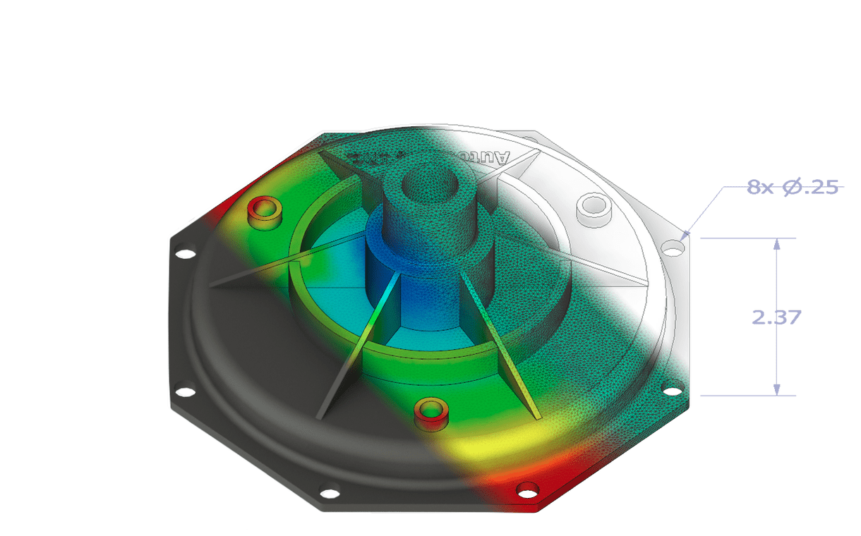
Part quality is shaped long before the first molded sample arrives. Flow resistance, trapped gas, uneven packing, and thermal imbalance can all affect final dimensions and surface finish. Fill, pack, and warp modules are widely used because they help predict those issues early and support better optimization, stronger engineering decisions, and more reliable product performance.
Overview of the Three Key Phases of Injection Molding Simulation
The phases of injection molding simulation are usually reviewed in this order:
Filling
Shows how the melt enters the cavity and how the flow front develops.
Packing
Shows how pressure compensates for cooling-related volume loss.
Warpage
Shows the final geometric change after cooling and differential shrinkage behavior are considered.
Filling Simulation Phase
The filling stage is the first stage where many molding risks become visible. A mold filling simulation shows whether the part can be filled completely, where pressure rises quickly, and where air or knit-related problems may form. In practice, this is the stage that gives the earliest feedback on manufacturability and machine demand.
Optimization in the Development Phase
A filling simulation is especially useful during early development because it reveals whether a part is realistic before toolmaking begins. It can show whether the cavity fills evenly, whether a weld line or air pocket is likely, whether clamp force and holding pressure targets look reasonable, and whether the selected gating concept supports the part geometry. Those findings affect machine size, mold stability, and overall cost, which is why injection molding filling work is so valuable at the concept stage.
Common Defects Identified in Filling Simulation
This stage is where engineers usually catch short shots, trapped air, weld lines, and flow imbalance first. A solid filling simulation does more than flag weak areas. It gives a structured study of where the material hesitates, where pressure drops too quickly, and where local geometry may need adjustment.
Packing Simulation Phase
The packing phase starts once the cavity is filled, and the machine continues applying pressure so additional melt can compensate for volume loss during cooling. That compensation only works while a liquid core still exists. Once the gate or sprue freezes, further feeding stops, and uneven density may begin to drive later distortion. This is why the packing phase has a direct effect on dimensional consistency and cycle time.
Results from a Pack Analysis
A pack analysis shows temperature history, pressure distribution, residual stress, volumetric shrink patterns, and the change in part mass as density evolves. Those results help estimate filling time, pack profile, holding time, melt and mold temperature, gate behavior, and runner performance. In practical terms, a good pack analysis turns the filling study into a more realistic view of what the cavity experiences after switch-over.
How Packing Settings Affect Final Part Density
In injection molding packing, settings such as switch-over timing and pressure profile strongly influence final density. If pack pressure is too low or ends too soon, sections farther from the gate may lose density and become more prone to sink or dimensional drift. If it is optimized well, the packing phase improves uniformity and supports more stable downstream results in the full injection molding process.
Warpage Analysis Phase
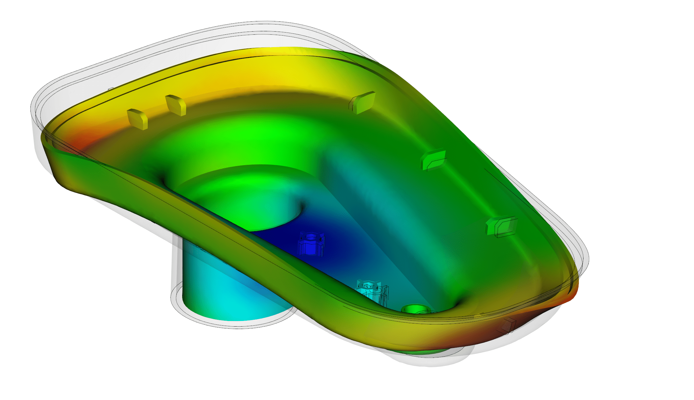
The warpage stage evaluates how the molded part changes shape as it cools to room temperature. This calculation uses results from earlier stages and can include thermal effects, packing effects, and orientation effects for fiber-reinforced grades. In software workflows, warpage simulation is the stage that connects filling and packing behavior to the final molded geometry.
Simulation of Shrinkage
Uneven shrinkage behavior is one of the main drivers of warpage. While packing can compensate for some volume loss, shrinkage continues as the part cools and solidifies. If that contraction is not uniform, the part stores stress and may move away from nominal geometry. A solid warpage simulation, therefore, starts with the local shrink patterns created in the earlier stages.
Distortion Minimization
The goal here is to see where distortion comes from and reduce it with targeted changes. Analysts typically compare differential cooling, differential shrinkage, and orientation-driven effects, then adjust gating, wall balance, pack settings, or thermal control. That is where a focused warp analysis becomes useful, because it points to the main cause instead of treating every deflection the same way.
Process Interactions Between Filling, Packing, and Warpage
These stages should never be read in isolation. Filling affects pressure demand and flow orientation. Packing changes density and residual stress. Warpage is the visible outcome of those earlier choices. That is why the strongest results come from reviewing the full set of phases of injection molding simulation rather than optimizing one step alone.
Discover how MF Software uses simulation to optimize your injection molding process before production begins.
Why Choose MF Software for Injection Molding Simulation Services
MF Software helps companies make simulation a regular part of daily project work, not just a late-stage check. The goal is to make technical analysis accessible for both managers and engineers.
Proven Expertise in Injection Molding Simulation
MF Software offers dedicated Moldflow-related consulting, training, and service support.
Simulation-Driven Optimization
We prioritize filling, packing, cooling, and warpage as linked levers for reducing risk before tooling investment.
Support From Design Validation to Production Readiness
We start our work by supporting part designers, toolmakers, and teams preparing for stable production.
FAQ
It is the stage after filling. During the packing phase, the machine keeps applying pressure so extra melt can compensate for cooling-related volume loss before the gate freezes.
Shrinkage is size reduction during cooling. Warpage is a shape change caused by uneven shrinkage or uneven thermal and orientation effects across the part.
They are filling, packing, and warpage. These injection molding simulation phases are often modeled as linked steps because each one influences the next.
Key parameters include fill time, flow-rate profile, injection pressure, clamp force, melt and mold temperature, and pack pressure profile and duration. These settings directly influence fill behavior, density distribution, and final part geometry.
Start by finding the main cause. Then adjust the gating, pack profile, wall balance, or cooling conditions based on the result plots and part behavior.
Common signs are bending, twisting, bowing, or dimensional drift after cooling. Those effects show that the part experienced uneven pressure, thermal history, or local shrinkage behavior.
It is the final part deformation after molding – the visible shape deviation caused by non-uniform contraction and related effects during cooling.