How to run a core shift analysis?
Did you know that you can run a core shift on either Core 3D or Part Insert 3D properties?
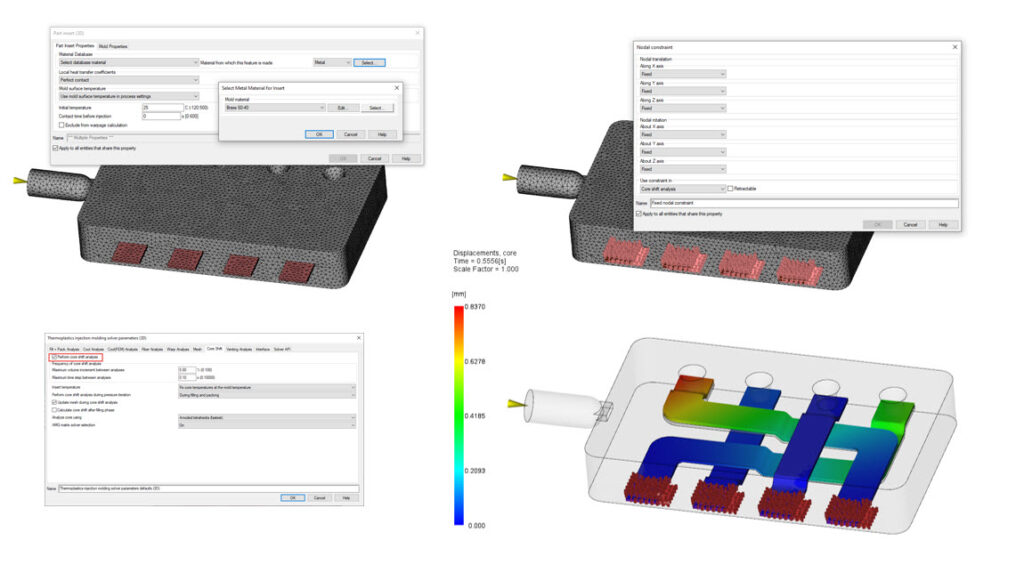
If the insert stays with the part post-molding, I consider that to be a part insert. If the insert stays with the mold, I would usually assign it to be a core or mold insert. You can set the properties on the CAD body or the meshed body.
Be sure to add constraints (Boundary Conditions – Constraints and Loads – Constraints) to the nodes that hold the insert in place within the mold. I typically used Fixed Constraints.
Next, be sure to turn on the Core Shift (Advanced Options – Solver Parameters – Edit – Core Shift).
Finally, you can look at the various core shift results like Displacement, Core, or either of the core shift stress plots.
If you are using a thermoset material, you need to use Microchip Encapsulation to run a paddle/core shift analysis.
How do you run a core shift analysis?